

| VERA array & stations | VERA System | Contact |
System & Stations
VERA System
Upper cabin / Dual-beam receiving systems
Two receivers are installed at the Cassegrain focus to observe two adjacent sources simultaneously. The two receivers are mounted on Stewart-mount platform and are steerable with a separation of two sources varying from 0.3 to 2.2 degrees.
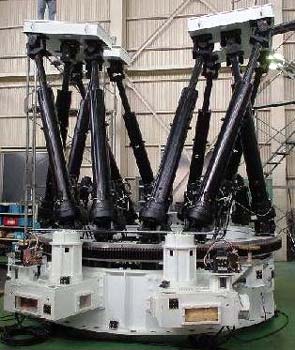
Dual-beam Steward-mount platform
Each platform is sustained by six arms. By changing arms' lengths, the receiver platform can be moved in the six dimensions (3-dimensional parallel motions and 3-dimensional rotations). The whole system can be rotated to track the apparent motion of stars due to the earth rotation.
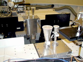
Receivers
Dual-beam receivers (silver box with two horns) are installed on the Steward-mount platforms. Each receiver has two conical horns, larger one for K (22 GHz) and smaller one for Q (43 GHz) band.
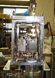
Inside view of the receiver dewer
Seen in the dewer are low-noise HEMT amplifiers. During the observation, the dewer is vacuumed and cooled down to 20 K to reduce the thermal noise.
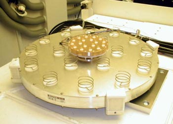
S / X-band Helical Array Feed
Instead of conical horn, low-profile helical arrays are used as feeds for S (2 GHz) and X (8 GHz) band. Apertures are synthesized with arrays of helices on the plates, providing similar performances as horns with the same apertures. S/X feeds are mainly used for geodetic observation to measure the precise station position.
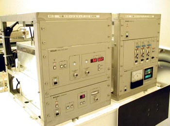
Local Oscillator
Standard frequency signals are generated in Local Oscillator and mixed with the radio-frequency (RF) signals from astronomical objects to down-convert the RF to an intermediate frequency (IF), which is much easier to handle.
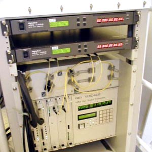
Sampler / Digital-opto transponder
The sampler digitizes the radio signals at the data rate of 2 Gbps (Giga-bit per second) for each beam. Digitized data are sent to the control building through optical-fibers.
| Dual-beam antenna << | | back to Map | | >> Lower cabin |